
Location: Home > Product > Voltage Power Regulator
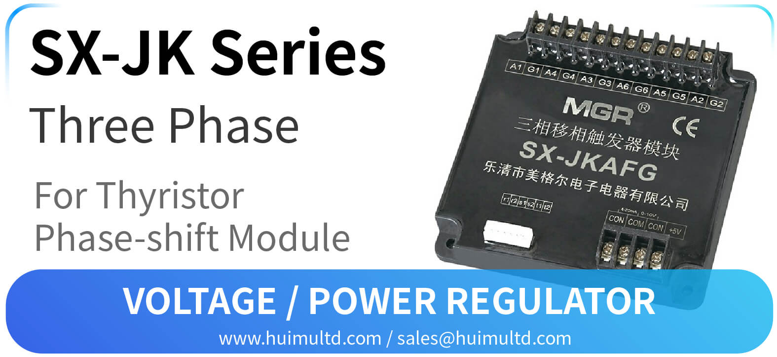
SX-JK Series
Voltage Power Regulator
[All the information on this website is for reference only, and the actual product and the accompanying product manual shall prevail. If you have any questions, please contact webmaster@huimultd.com]
Introduction
SX-JK Series Three Phase Solid State Phase-Shift Trigger Module is a device designed to regulate the load voltage through three phase thyristor circuits, and it integrates the three phase phase-detection circuit, the phase-shift circuit, the control circuit and the trigger circuit. Our TB Series three phase synchronous transformer module (co-sold with SX-JK Series) provides the synchronous signal and internal operation power supply for the phase-shift module, so users have no needs for any external circuit or power supply. SX-JK Series can change the conduction angle of thyristors automatically (E type: CON 0-5V; F type: CON 0-10V; G type: CON 4-20mA; H type: CON 1-5V) or manually (adjustment of potentiometer) to trigger the corresponding components to achieve the purpose of phase-shift and voltage-regulation. According to the function, SX-JK Series can be divided into SX-JKA Series (three phase SCR type phase-shift trigger module), SX-JKT (three phase TRIAC type phase-shift trigger module), SX-JKZ (three phase fully-controlled rectification phase-shift trigger module) and SX-JKB (three phase half-controlled rectification phase-shift trigger module).
How to order
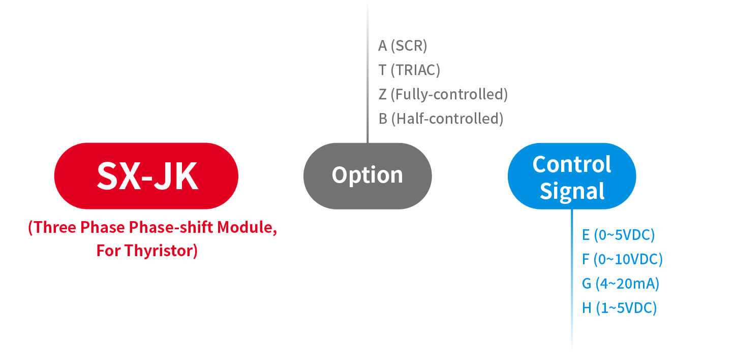
SX-JK (Three Phase Phase-shift Module, For Thyristor)
- [Option] {A (SCR); T (TRIAC); Z (Fully-controlled); B (Half-controlled)}
- [Control Signal] {E (0~5VDC); F (0~10VDC); G (4~20mA); H (1~5VDC)}Parameters
SX-JK Series
Control Signal: E: CON 0~5V; F: CON 0~10V; G: CON 4~20mA; H: CON 1~5V
*(E, F, H types can be controlled by the manual control circuit, G type cannot be adjusted with the potentiometer)
Power Source: TB-3A/TB-3Z (three phase synchronous transformer module) can provide working power for SX-JK without additional circuit or external power
Load Voltage: Three phase, 380VAC (300VAC~420VAC), 50HZ
Load Current: Refer to the rated current of the selected solid state relay
Dimensions & Mounting: 107mm*107mm*30mm; Panel mount solid state module with plastic cover and screw terminalsFeatures
● Modularization with high pressure resistant, safer and more reliable
● Miniaturization with convenience for installation, wiring and etc.
● Linear phase-shift control circuit with good stability and high precision
● LED status indicatorDimensions and Circuit Wiring Diagram
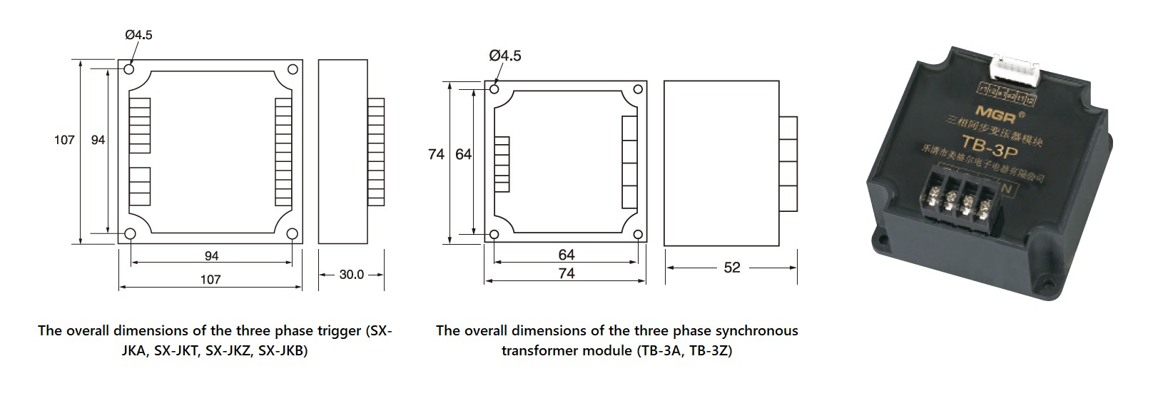
Dimensions
SX-JKA Series (SCR, Phase-Shift)
With the support of the three phase voltage regulation synchronous transformer module (TB-3A), SX-JKA can continuously adjust the AC output voltage through the circuit composed of three sets of reverse-parallel SCR thyristors.
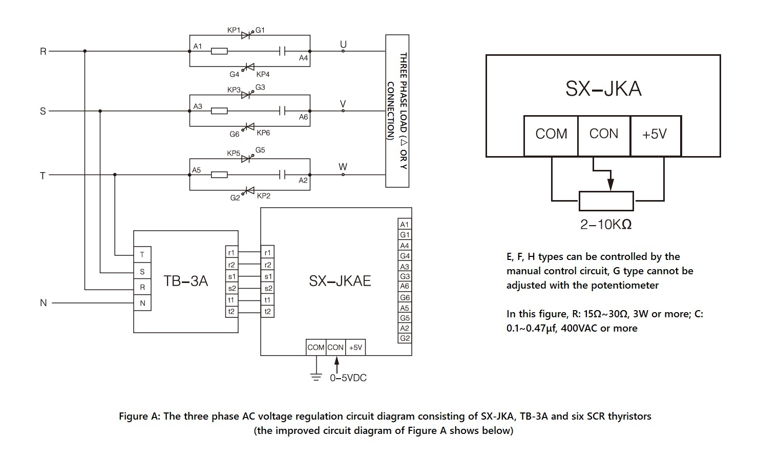
SX-JKA Series, Circuit Wiring Diagram
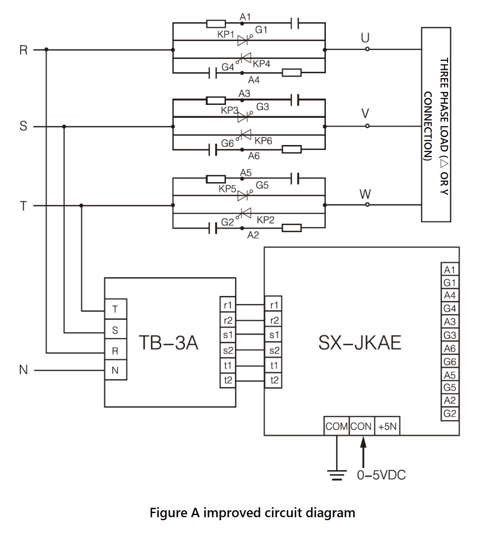
SX-JKA Series, Circuit Wiring Diagram, dv/dt improved version
SX-JKT Series (TRIAC, Phase-Shift)
With the support of the three phase voltage regulation synchronous transformer module (TB-3A), SX-JKT can continuously adjust the AC output voltage through the circuit composed of three TRIAC thyristors (generally only for the resistive load).
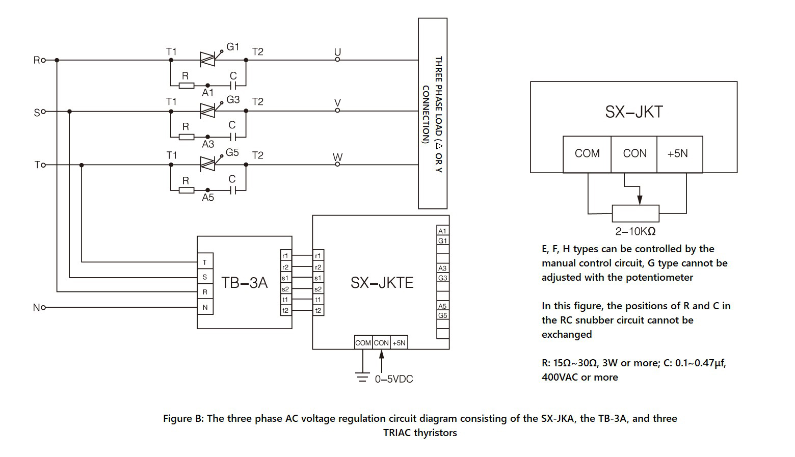
SX-JKT Series, Circuit Wiring Diagram
SX-JKZ Series (Fully-Controlled, Rectification, Phase-Shift)
With the support of the three phase rectification synchronous transformer module (TB-3Z), SX-JKZ can continuously adjust the AC output voltage of the three phase fully-controlled rectification circuit.
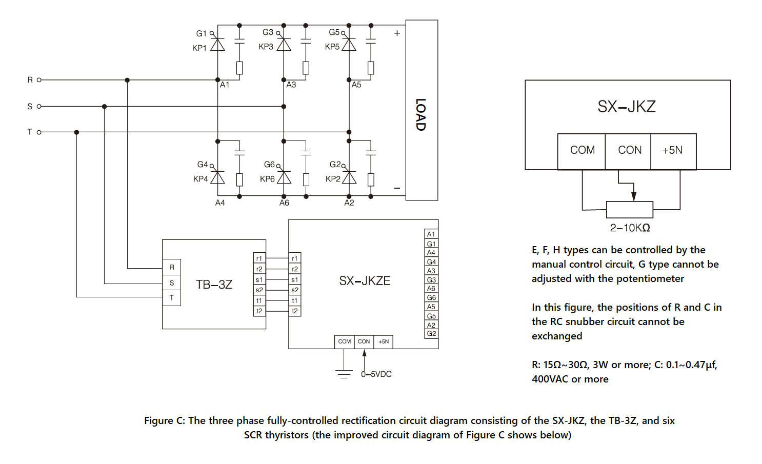
SX-JKZ Series, Circuit Wiring Diagram
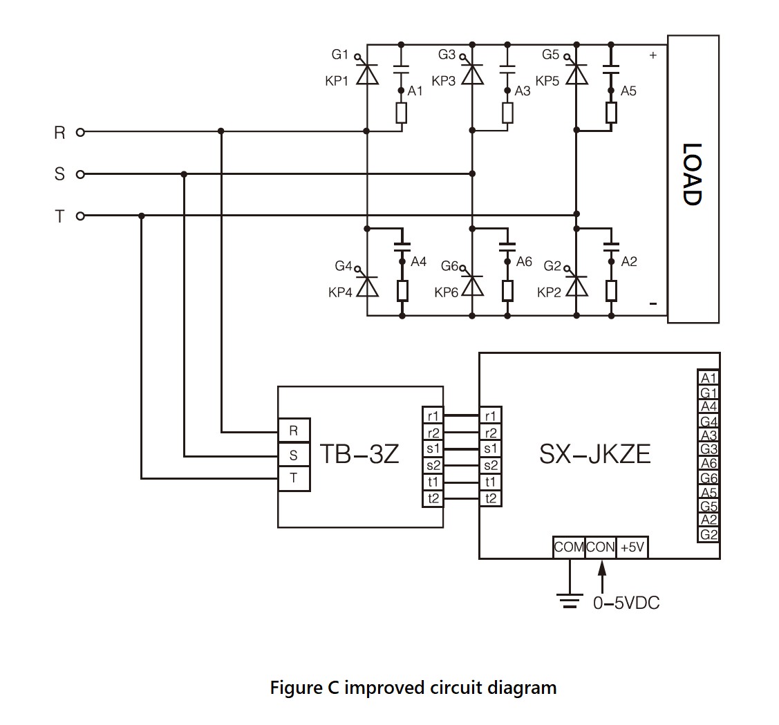
SX-JKZ Series, Circuit Wiring Diagram, dv/dt improved version
SX-JKB Series (Half-Controlled, Rectification, Phase-Shift)
With the support of the three phase rectification synchronous transformer module (TB-3Z), SX-JKB can continuously adjust the AC output voltage of the three phase half-controlled rectification circuit.
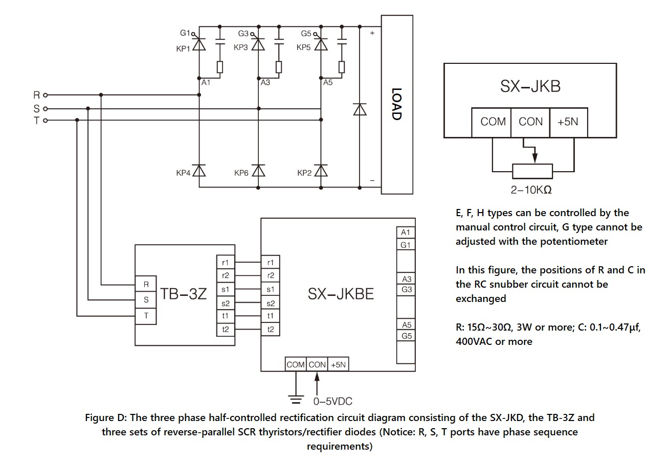
SX-JKB Series, Circuit Wiring Diagram
Application
● Applications that need three phase voltage adjustment.
● For power thyristor circuit.Precautions and FAQs
● The three phase AC voltage regulation circuit has no phase sequence requirements, but the three phase input cables (R, S, T) in the three phase rectifier circuit has phase sequence requirements. Besides, the input cables and the thyristor (such as R corresponding to the anode of KP1 and the cathode of KP4), the synchronous transformer module and the three phase trigger must be strictly one-to-one correspondence, otherwise the system will not work normally.
● The trigger terminals of the three phase trigger (such as A1, G1, ..., A6, G6) adopt the strong current trigger mode, which can trigger any SCR thyristor within 1000A current. The connection method of the so-called strong current trigger mode is to connect A1 and G1 (corresponding to the anode and gate of KP1) instead of the usual cathode and gate.
● The power grid voltage in the four application circuits (Figures A, B, C, D) must be 380VAC (300~420VAC), 50Hz. If the module is used in the low voltage application (requires full isolation step-down transformer), customers need to contact us for customization.
● CON must be positive relative to COM, and if the polarity is opposite, the output terminal will be out of control (fully open or fully closed). When the control terminal CON changes from 0V to 5V, the voltage on the AC load can be adjusted from 0V to the maximum value (for resistive loads). When the control voltage on CON is around 0V~0.8V (Fully-closed Region), the control signal can reliably shut down the output of the module. When the control voltage on CON is around 0.8V~4.6V (Adjustable Region), the conduction angle α decreases linearly from 180° to 0° as the control voltage increases, and the voltage on the AC load increases from 0V to the maximum value. When the control voltage on CON is around 4.6V~5V (Full-open Region), the voltage on the AC load is the maximum value (close to the power grid voltage).
● The input impedance between CON and COM is divided into E, F and H type (the impedance of these three types are greater than or equal to 30KΩ), and G type (the impedance is 250Ω). The +5V voltage signal is only provided for the manual potentiometer (the selected resistance is between 2~10KΩ), not for other uses. Note: The G type (4~20mA as control signal) cannot be manually adjusted by the potentiometer, so the +5V port is useless for the G type.
● The power of the three phase load should be balanced. When the load uses the Y-connection method, the center point Y can be connected or not connected to the neutral line. However, the high-order harmonic interference to the power grid when connected to the neutral line is larger than that when not connected to the neutral line. The N line on the synchronous transformer TB-3A must be reliably connected to the earth ground (the neutral line).
● In the three phase rectifier circuit, when the output terminal of the module is connected in parallel with an electrolytic capacitor to filter, the voltage across the capacitor cannot be abruptly changed, so in this high-voltage and large-capacity case, the thyristor will be damaged due to overcurrent. Therefore, before the module is powered on, it must ensure that the voltage on the control terminal CON is 0V, and after power-on, the voltage on the control terminal CON must be gradually increased from 0V to ensure the minimum surge current of the capacitor.
● The speed control of the three phase AC asynchronous motor should be adjusted by the frequency converter, while the three phase voltage regulation module can only be applied to fan motors and pump motors where the requirements are not high. For the soft start of the three phase motors, the voltage/current closed-loop control system should be used.
● The performance of the weak current part of the three phase thyristor phase-shift trigger module is stable and reliable, and the consistency of the six channels (or three channels) trigger is also very good. However, the three phase thyristor phase-shift trigger module adopts the strong current trigger mode, so if any thyristor in the main circuit malfunctions (the gate is damaged) and cannot be triggered, the corresponding trigger terminal on the three phase thyristor phase-shift trigger module will be easily damaged. This is the main deficiency of this module.
● In the main circuit, an RC snubber circuit must be added between the anode and the cathode of the thyristor for protection. The resistance of the RC circuit is generally 15~30Ω, 3W or more, and the capacitance is 0.1~0.47μf, 400VAC or more.
● SX-JKA, SX-JKT, SX-JKZ, SX-JKB, TB-3A, and TB-3Z generate very little heat and do not need to be mounted on a heat sink.
● The synchronous transformer is sold together with three phase thyristor phase-shift trigger module.
● What is the Phase Shift Control?
Phase shift control (also known as phase control, phase angle control, or conduction angle control) ,which controls the output voltage by controlling the phase of the trigger circuit. For an output circuit consisting of two anti-parallel (back-to-back) SCRs (each SCR is responsible for a half cycle of power output, and its phase angle can be controlled by the control signal), by changing the phase angle, the SCR will run ahead or delay during its duty cycle. If changing the phase angle of SCRs from 180° to 0°, the AC output voltage (effective value, or rms value) can be smoothly adjusted from zero to maximum.All Regular Models We Offer
● SX-JKA Series (Three Phase)
- SX-JKAE
- SX-JKAF
- SX-JKAG
- SX-JKAH
● SX-JKT Series (Three Phase)
- SX-JKTE
- SX-JKTF
- SX-JKTG
- SX-JKTH
● SX-JKZ Series (Three Phase)
- SX-JKZE
- SX-JKZF
- SX-JKZG
- SX-JKZH
● SX-JKB Series (Three Phase)
- SX-JKBE
- SX-JKBF
- SX-JKBG
- SX-JKBH
(E type: CON 0-5V; F type: CON 0-10V; G type: CON 4-20mA; H type: CON 1-5V)
*Customized models are available, be free to contact us.
Tips
1) When selecting the rated current of the solid state relay/solid state module, please consider the corresponding Derating Factor.
2) You can visit Blog - Resource to view and download files.
3) You can visit Products to view and learn about other products.
4) You can visit Information to view and learn about solid state relays/solid state modules knowledge.
5) You can also visit Help, or Contact us to get more support.
Get in touch with us now!
Please take a minute or two to complete this simple form to get reply in 24 hours, thank you!
*Please check the trash box of your mailbox, if you do not receive our email.


