
Location: Home > Product > Voltage Power Regulator
SCR-JKK, TRIAC-JKK Series
Voltage Power Regulator
[All the information on this website is for reference only, and the actual product and the accompanying product manual shall prevail. If you have any questions, please contact webmaster@huimultd.com]
Introduction
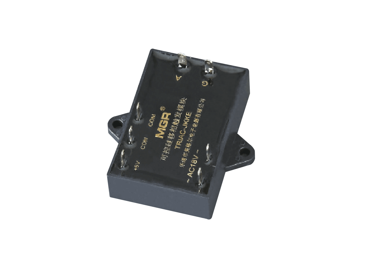
SCR-JKK, TRIAC-JKK Series Single Phase Solid State Phase-Shift Trigger Module is a device designed to regulate the load voltage through power thyristor circuits, and it has built-in synchronous transformer, synchronous phase detection circuit, phase shift circuit (phase control circuit) and trigger circuit. SCR-JKK Series single phase SCR thyristor phase-shift trigger module is used for power SCR circuit; TRIAC-JKK Series single phase TRIAC thyristor phase-shift trigger module is used for power TRIAC circuit or two sets of SCR circuit. The principle of the single phase thyristor phase-shift trigger module is: The phase of the power grid will be taking as the synchronization reference, and by change the magnitude of the control voltage, a trigger pulse signal will be generated in the module, and then this signal will be sent to the output terminal (A, G ports) by the optical isolation method to trigger the corresponding thyristors to achieve the purpose of phase-shift and voltage-regulation. The control part of the phase-shift trigger is optically isolated from the output terminal of the trigger, so it can be controlled automatically (E type: CON 0-5V; F type: CON 0-10V; G type: CON 4-20mA; H type: CON 1-5V) or manually (adjustment of potentiometer). Because it only needs a 18VAC synchronous voltage from the power grid, and the electrodes are connected by inserts, SCR-JKK Series and TRIAC-JKK Series are extremely convenient to use.
How to order
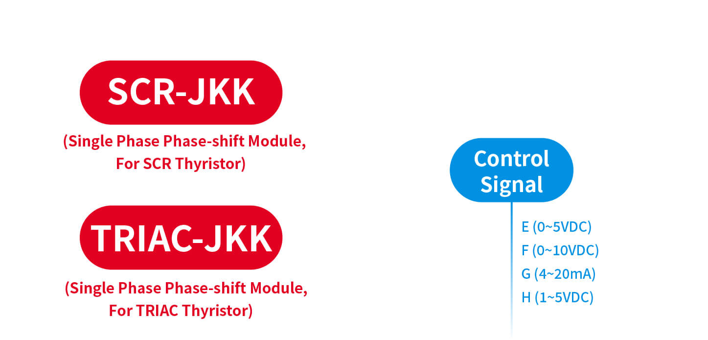
[Series] {SCR-JKK (Single Phase Phase-shift Module, For SCR Thyristor); TRIAC-JKK (Single Phase Phase-shift Module, For TRIAC Thyristor)}
- [Control Signal] {E (0~5VDC); F (0~10VDC); G (4~20mA); H (1~5VDC)}Parameters
SCR-JKK, TRIAC-JKK Series
Control Signal: E: CON 0-5V; F: CON 0-10V; G: CON 4-20mA; H: CON 1-5V
*(E, F, H types can be controlled by the manual control circuit, G type cannot be adjusted with the potentiometer)
Power Source: Internal synchronous transformer can provide working power and synchronous voltage (18VAC) for SCR-JKK/TRIAC-JKK without additional circuit or external power
Load Voltage: Single phase, 220VAC
Load Current: Refer to the rated current of the selected solid state relay
Dimensions & Mounting: 56mm*56mm*16mm; Panel mount solid state module with plastic cover and plug-in terminalsFeatures
● Modularization with high pressure resistant, safer and more reliable
● Miniaturization with convenience for installation, wiring and etc.
● Linear phase-shift control circuit with good stability and high precision
● Integrates the synchronous transformer, the phase detection circuit, the phase-shift trigger circuit.
● No external 18VAC power supply required
● LED status indicatorDimensions and Circuit Wiring Diagram
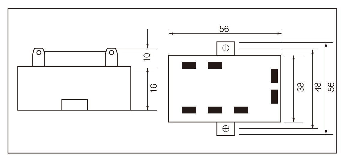
SCR-JKK, TRIAC-JKK Series, Dimensions
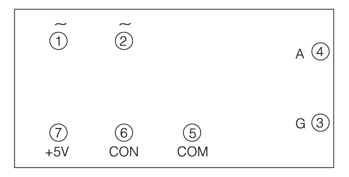
SCR-JKK, TRIAC-JKK Series, Ports
● The ① and ② ports are connected to the 18VAC secondary winding of the synchronous transformer to offer the power supply and the synchronous reference for the phase-shift trigger.
● The ③ port is connected to the trigger gate of the thyristor.
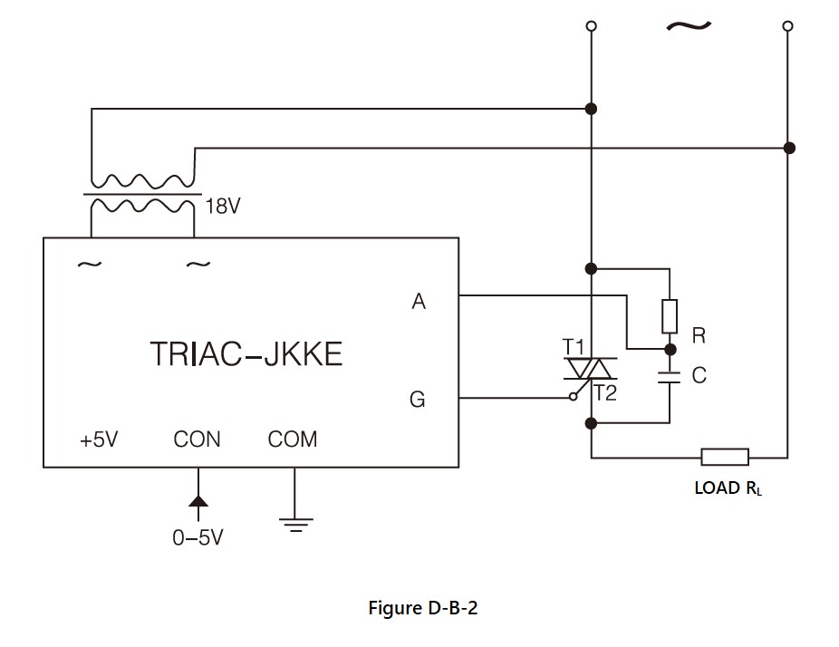
● The ④ port is connected to the anode of the SCR thyristor or the main electrode T1 of the TRIAC thyristor.
● The ⑤ port is the internal common ground terminal. If the phase-shift trigger is controlled by the external automatic control circuit, the ⑤ port will be connected to the ground of the external control circuit.
● The ⑥ port is the control terminal. When there is a 0.5V voltage signal inputted to the ⑥ port, the thyristor on the ③ and ④ ports will be triggered in the phase-shift range of 180°~0°.
● The ⑦ port is the +5V voltage terminal generated inside the module. If the ⑤, ⑥, ⑦ ports are connected to the external potentiometer to apply the manual control method, the ⑦ port acts as the power supply for it; if the control signal is provided by external control circuit to apply the automatic control method, the ⑦ port should be left floating.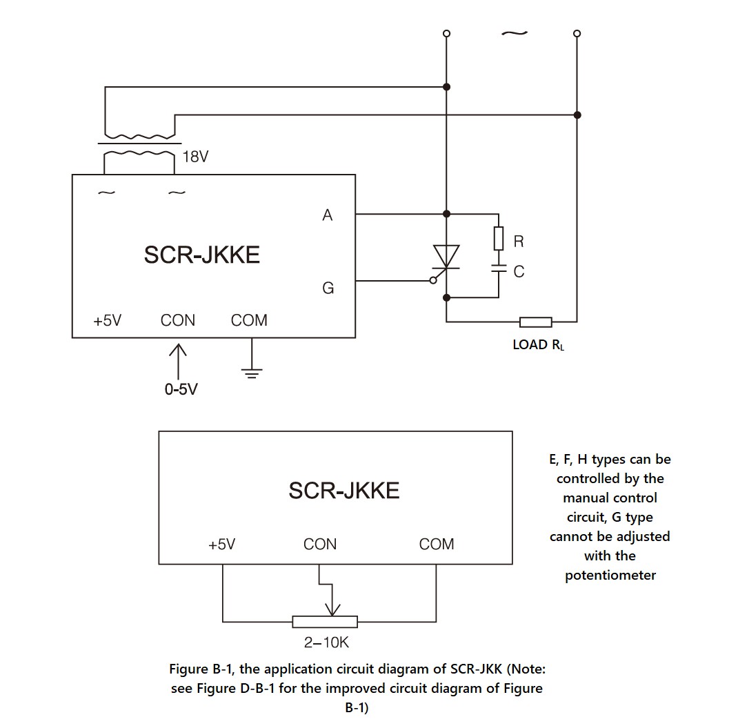
SCR-JKK Series, Circuit Wiring Diagram (1)
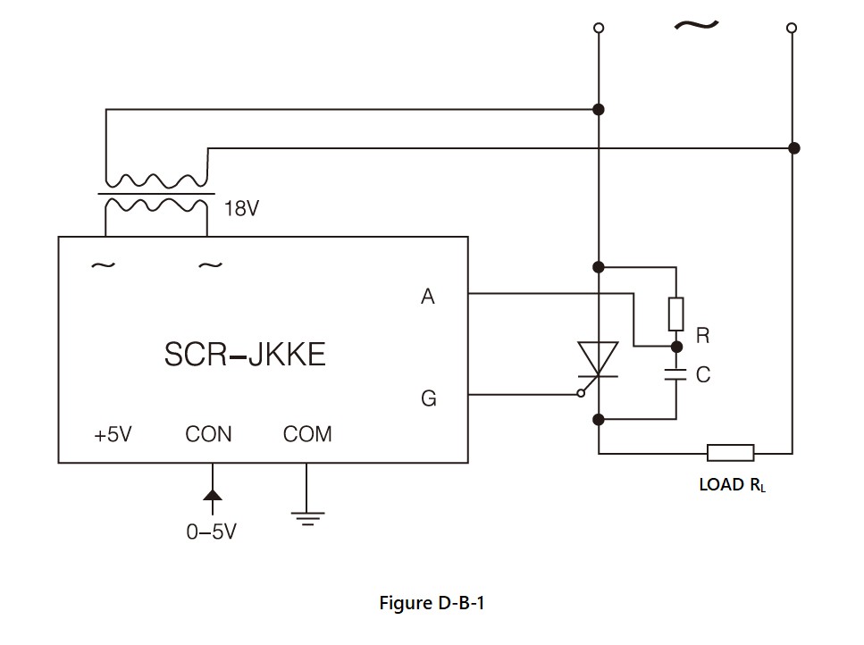
SCR-JKK Series, Circuit Wiring Diagram (1), dv/dt improved version
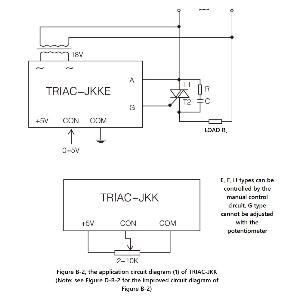
TRIAC-JKK Series, Circuit Wiring Diagram (1)
TRIAC-JKK Series, Circuit Wiring Diagram (1), dv/dt improved version
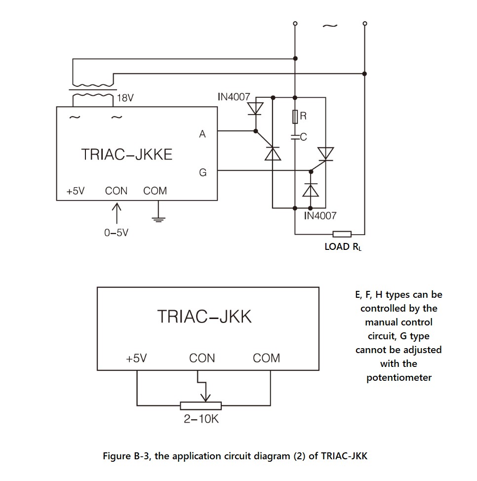
TRIAC-JKK Series, Circuit Wiring Diagram (2)
I/O waveform
The relationship and waveform of the control voltage UCON and the conduction angle α of the thyristor (when resistive load) shows below:
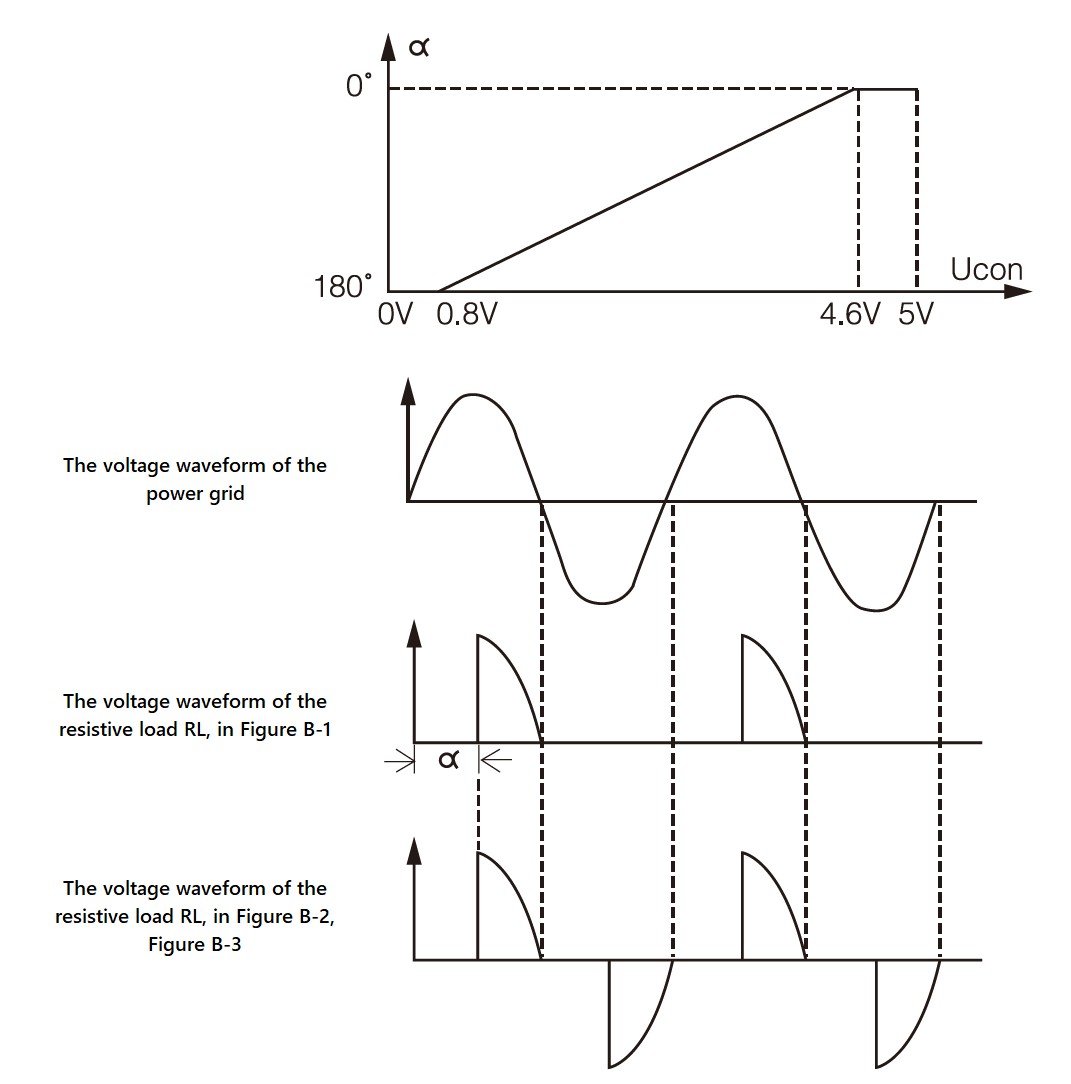
SCR-JKK, TRIAC-JKK Series, I/O waveform
Application
● Applications that need single phase voltage adjustment.
● For power thyristor circuit.Precautions and FAQs
● CON must be positive relative to COM, and if the polarity is opposite, the output terminal will be out of control (fully open or fully closed). When the control terminal CON changes from 0V to 5V, the voltage on the AC load can be adjusted from 0V to the maximum value (for resistive loads). When the control voltage on CON is around 0V~0.8V (Fully-closed Region), the control signal can reliably shut down the output of the module. When the control voltage on CON is around 0.8V~4.6V (Adjustable Region), the conduction angle α decreases linearly from 180° to 0° as the control voltage increases, and the voltage on the AC load increases from 0V to the maximum value. When the control voltage on CON is around 4.6V~5V (Full-open Region), the voltage on the AC load is the maximum value (close to the power grid voltage).
● The input impedance between CON and COM is divided into E, F and H type (the impedance of these three types are greater than or equal to 30KΩ), and G type (the impedance is 250Ω).
● The phase-shift trigger module can be applied to 100~420VAC, 50Hz power grid (below 100V can be customized).
● ① and ② ports are connected to the secondary winding of the synchronous transformer, which allows a voltage of 18VAC ± 5VAC and a power of 2W.
● The +5V voltage signal on ⑦ port is only provided for the manual potentiometer (the selected resistance is between 2~10KΩ), not for other uses. Note: The G type (4~20mA as control signal) cannot be manually adjusted by the potentiometer, so the +5V port is useless for the G type.
● The phase-shift trigger module can trigger thyristors within 1000A current (please pay attention to the connection method of the trigger terminal).
● The phase-shift trigger itself generates very little heat and does not require additional heat dissipation.
● What is the Phase Shift Control?
Phase shift control (also known as phase control, phase angle control, or conduction angle control) ,which controls the output voltage by controlling the phase of the trigger circuit. For an output circuit consisting of two anti-parallel (back-to-back) SCRs (each SCR is responsible for a half cycle of power output, and its phase angle can be controlled by the control signal), by changing the phase angle, the SCR will run ahead or delay during its duty cycle. If changing the phase angle of SCRs from 180° to 0°, the AC output voltage (effective value, or rms value) can be smoothly adjusted from zero to maximum.All Regular Models We Offer
● SCR-JKK Series (Single Phase)
- SCR-JKKE
- SCR-JKKF
- SCR-JKKG
- SCR-JKKH
● TRIAC-JKK Series (Single Phase)
- TRIAC-JKKE
- TRIAC-JKKF
- TRIAC-JKKG
- TRIAC-JKKH
(E type: CON 0-5V; F type: CON 0-10V; G type: CON 4-20mA; H type: CON 1-5V)
*Customized models are available, be free to contact us.
Tips
1) When selecting the rated current of the solid state relay/solid state module, please consider the corresponding Derating Factor.
2) You can visit Blog - Resource to view and download files.
3) You can visit Products to view and learn about other products.
4) You can visit Information to view and learn about solid state relays/solid state modules knowledge.
5) You can also visit Help, or Contact us to get more support.
Get in touch with us now!
Please take a minute or two to complete this simple form to get reply in 24 hours, thank you!
*Please check the trash box of your mailbox, if you do not receive our email.


