How to wire the electrical motor controller?
INTRODUCTION:
MGR electrical motor controller can be divided into MGR motor direction controller and MGR motor rotation speed controller. MGR motor direction controller is a kind of DPDT solid state relay, which can be used to replace complex electromagnetic relay systems and directly use digital signals to control the rotation of electrical motor. MGR DC motor speed control solid state relays can adjust the speed of the DC motor by adjusting the input power of the DC motor.
Through this article you will learn how to wire the MGR/mager electrical motor controller? How to wire the motor direction controller? How to wire the DC motor speed controller?
You can quickly navigate to the chapters you are interested in through the Directory below, and the Quick Navigator on the right side of the browser.
CONTENTS
§1. How to wire AC Reversible-Motor Solid State Relay? |
§2. How to wire DC Reversible-Motor Solid State Relay? |
§3. How to wire DC Motor Speed Control Solid State Relay? |
§1. How to wire AC Reversible-motor Solid State Relay?
-AC Bi-directional Motor Direction Controller Wiring Diagram
1.1 Single Phase AC Reversible-motor Solid State Relay
MGR-1M Series
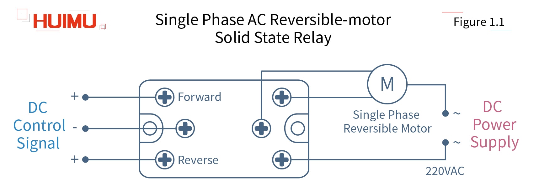
The single phase AC reversible-motor solid state relay is a single phase AC forward and reverse switch which uses the DC control signal to control the single phase AC reversible electric motor (with forward/reverse rotation direction). The three-terminals input circuit of the single phase AC motor direction control solid state relay is connected to the DC control signal, and one of which is the common terminal, and the other two are direction terminals that receive the direction control signal from the control device. The three-terminals output circuit of the single phase AC motor direction control solid state relay is connected to the single-phase AC power supply and the single phase AC reversible electric motor. One of which is the common terminal, and the other two are used to control the forward rotation and reverse rotation of the single phase AC reversible electric motor.
1.2 Three Phase AC Reversible-motor Solid State Relay
MGR-3M Series
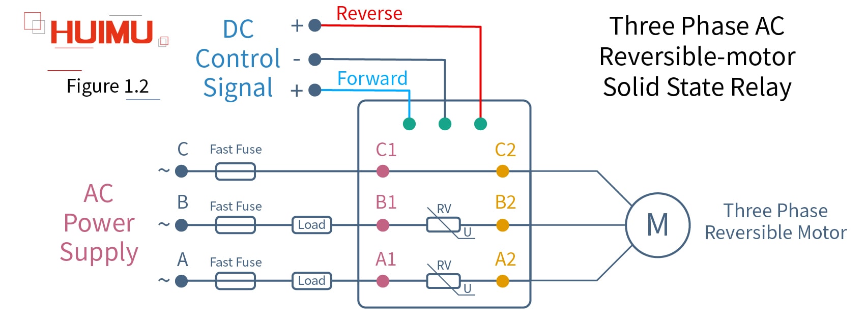
The three phase AC reversible-motor solid state relay is a three phase AC forward and reverse switch which uses the DC control signal to control the three phase AC reversible electric motor (with forward/reverse rotation direction). The three-terminals input circuit of the three phase AC motor direction control solid state relay is connected to the DC control signal, and one of which is the common terminal, and the other two are direction terminals that receive the direction control signal from the control device. There are six terminals in the output circuit. Terminal A1, B1, C1 are connected to the three-phase AC power supply, and terminal A2, B2, C2 are connected to the three phase AC reversible electric motor.
§2. How to wire DC Reversible-Motor Solid State Relay?
-DC Bi-directional Motor Direction Controller Wiring Diagram
MGR-DHK Series
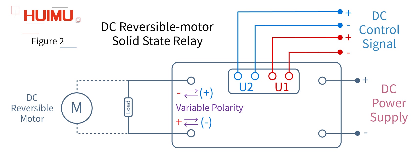
The DC reversible-motor solid state relay is a DC forward and reverse switch which uses the DC control signal to control the DC reversible electric motor (with forward/reverse rotation direction). The four-terminals input circuit of the DC motor direction control solid state relay is connected to the DC control signal, which can be divided into two groups: U1 and U2, which are respectively used to control the rotation direction of the DC reversible electric motor. There are four terminals in the output circuit. Two of which are connect to the DC power supply, and the other two are load terminals, which are connected to the DC load or the DC reversible electric motor. The load terminals have variable polarity and can be exchanged according to the DC control signal. For example, if it is assumed that U1 is the forward control terminal and U2 is the reverse control terminal, then when there is control signal applied on U1, the output current flows from the "+" port (red) to the "-" port (red), and the DC reversible electric motor will rotate forward; when there is control signal applied on U2, the polarity of load terminals will be exchanged, then the output current flows from the "+" port (blue) to the "-" port (blue), the DC reversible electric motor will rotate in reverse. Vice versa.
§3. How to wire DC Motor Speed Control Solid State Relay?
-DC Motor Speed Control Solid State Relay Wiring Diagram
MGR-DTSV Series
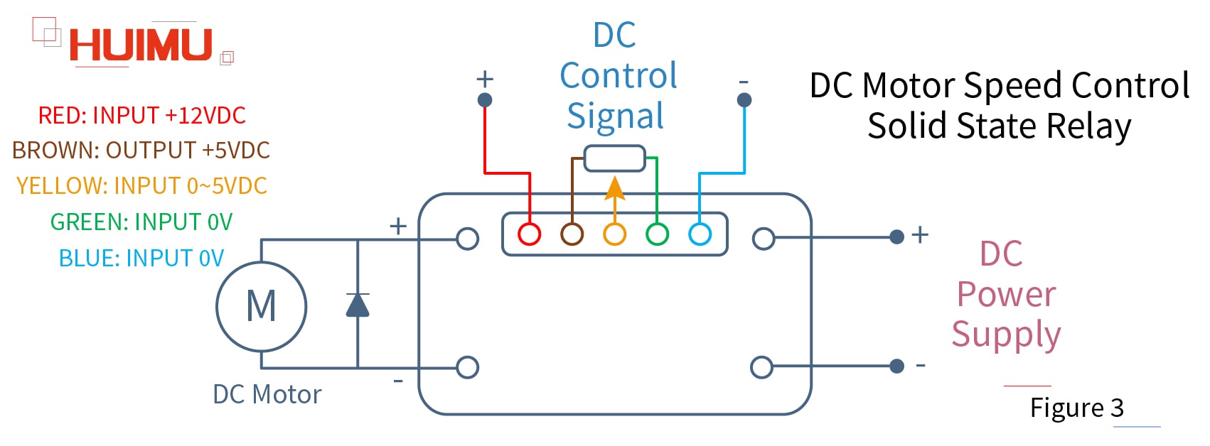
The DC motor speed control solid state relay is a kind of the DC thyristor motor speed control switch (or DC motor speed controller), which can realize stepless variable speed control for the DC variable speed motor, that is, adjust the speed of the DC variable speed motor. The input circuit of the DC motor speed control solid state relay has five terminals. The RED and BLUE terminals provide the power for the input circuit. The BRWON, YELLOW and GREEN terminals form a sliding rheostat that adjusts the rotation speed of the DC variable speed motor by adjusting the resistance. The output circuit of the DC motor speed control solid state relay has four terminals, two of which are connected to the DC power supply, and the other two are connected to the DC variable speed motor.

Get in touch with us now!
Please take a minute or two to complete this simple form to get reply in 24 hours, thank you!
*Please check the trash box of your mailbox, if you do not receive our email.


