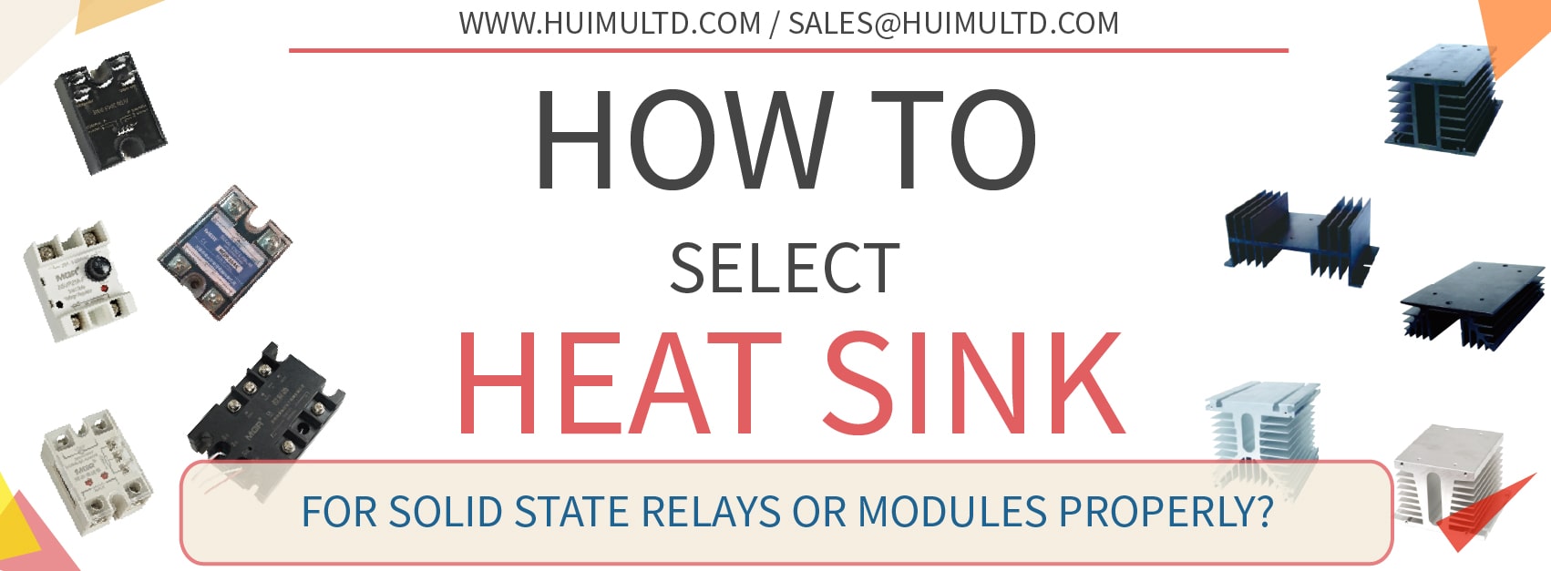
How to select a suitable Heat Sink for Solid State Relays and Solid State Modules?
INTRODUCTION:
Solid state relays/modules generate heat when they are in operation. Choosing the right heat sink/radiator helps to increase the efficiency and service life of solid state relays/modules.
Through this article you will learn how does the heat sink/radiator work? What is the heat calculation formula of the solid state relay/module? How to select a suitable heat sink for solid state relays and solid state modules?
You can quickly navigate to the chapters you are interested in through the Directory below, and the Quick Navigator on the right side of the browser.
CONTENTS
§1. How the Heat Sink/Radiator works? |
§2. How to calculate the Heat? |
§3. How to select Heat Sink/Radiator? |
§1. How the Heat Sink/Radiator works?
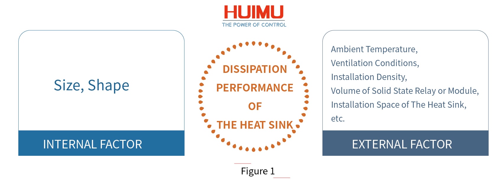
The role of the heat sink/radiator is to dissipate the heat generated by the solid state relay or module to ensure that the solid state relay or module will work stably and reliable at optimum conditions and not be burned and damaged due to high temperatures. The heat dissipation effect of the heat sink is not only related to its specification (size, shape), but also related to external environmental factors, such as the ambient temperature (season), ventilation conditions (natural cooling or forced cooling, and ventilation volume), and installation density. In addition, it is also necessary to consider whether the volume of the solid state relay or the module itself and the installation space of the heat sink in the equipment matches the specifications of the heat sink.
The cooling method of the solid state relay/module can be divided into Air Cooling method and Water Cooling method. And the air cooling method can be farther divided into Natural Cooling (use Heat Sink) and Forced Cooling by Fan (use Air Cooled Radiator). Normally, if the load current of the solid state relay/module reaches 10A, a heat sink must be equipped; if the load current is 40A or more, an air-cooled radiator or a water-cooled radiator must be installed. When the module is used for the device with load power greater than 15KW, it is recommended to use a suitable heat sink, and apply thermal grease between the heat sink and the SCR backplane, and cooling down it by cold air. If the current is below 350A, the module is cooled by forced air cooling; if the current is more than 400A, the cooling method for the module can be either air-cooling or water-cooling.
Heat dissipation reference standard: The temperature of the backplane (the side in contact with the heat sink) of the solid state relay or module should not exceed 80 °C.
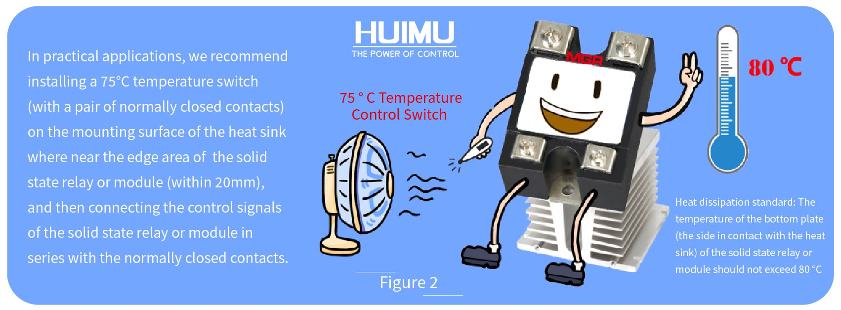
In practical applications, we recommend installing a 75°C temperature switch (with a pair of normally closed contacts) on the mounting surface of the heat sink where near the edge area of the solid state relay or module (within 20mm), and then connecting the control signals of the solid state relay or module in series with the normally closed contacts. In this way, when the temperature of the detection point exceeds 75 °C, the normally closed contact will trip and cut off the control signal, and the output terminal of the solid state relay or module will be forcibly turned off to get protection. Generally, if the solid state relay or module is installed to the place with the actual current of each phase exceeding 50A, the high installation density and ambient temperature, it is better to apply a temperature switch for protection to ensure that the temperature of the backplane of the solid state relay or module does not exceed 80 ° C under severe conditions.
§2. How to calculate the Heat?
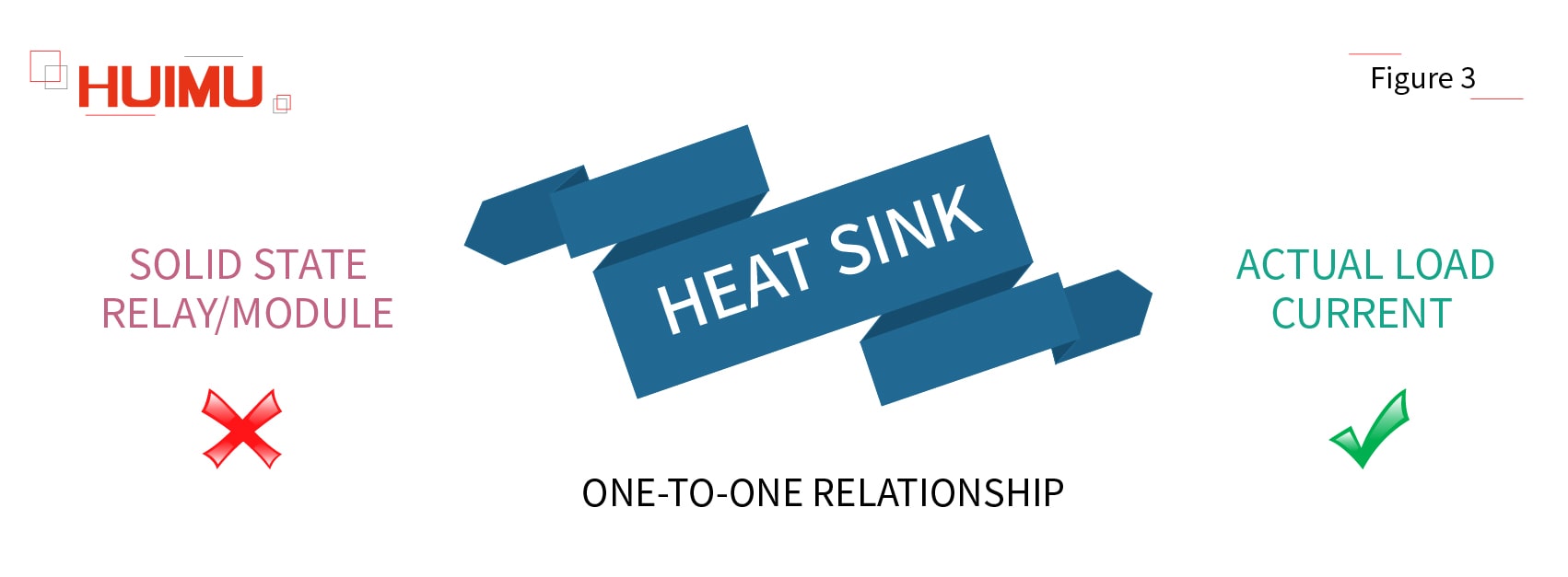
At first, we should know that there is no one-to-one correspondence between the model (type) of the heat sink and the model (type) of the solid state relay or module. Since solid-state relays use transistors as electronic switching components/power components, the heat generated by the solid state relay or module is mainly related to the actual current of the load it drives, instead of its own rated current specification (current grade).
The heat generated by the solid state relay/module in practical applications can be calculated by the following formula:
1. Heat = Actual Load Current (Amps) * 1.5 W/Amps
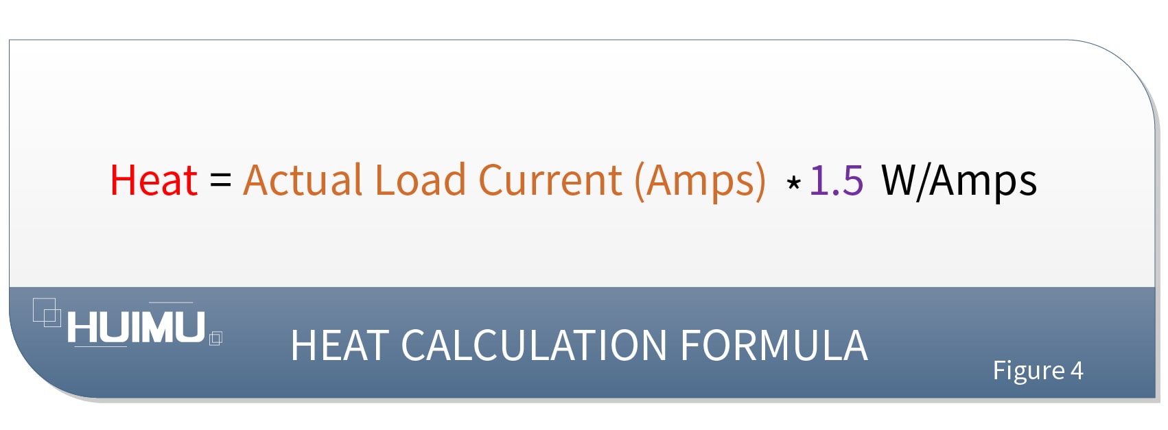
Note: The above formula is suitable for single phase solid state relays, single phase AC voltage regulator modules, and R series solid state voltage regulators. For three phase solid state relays and three phase AC voltage regulator modules, the actual load current should be the sum of the load currents of each phase.
2. Heat = Actual Load Current (Amps) * 3.0 W/Amps
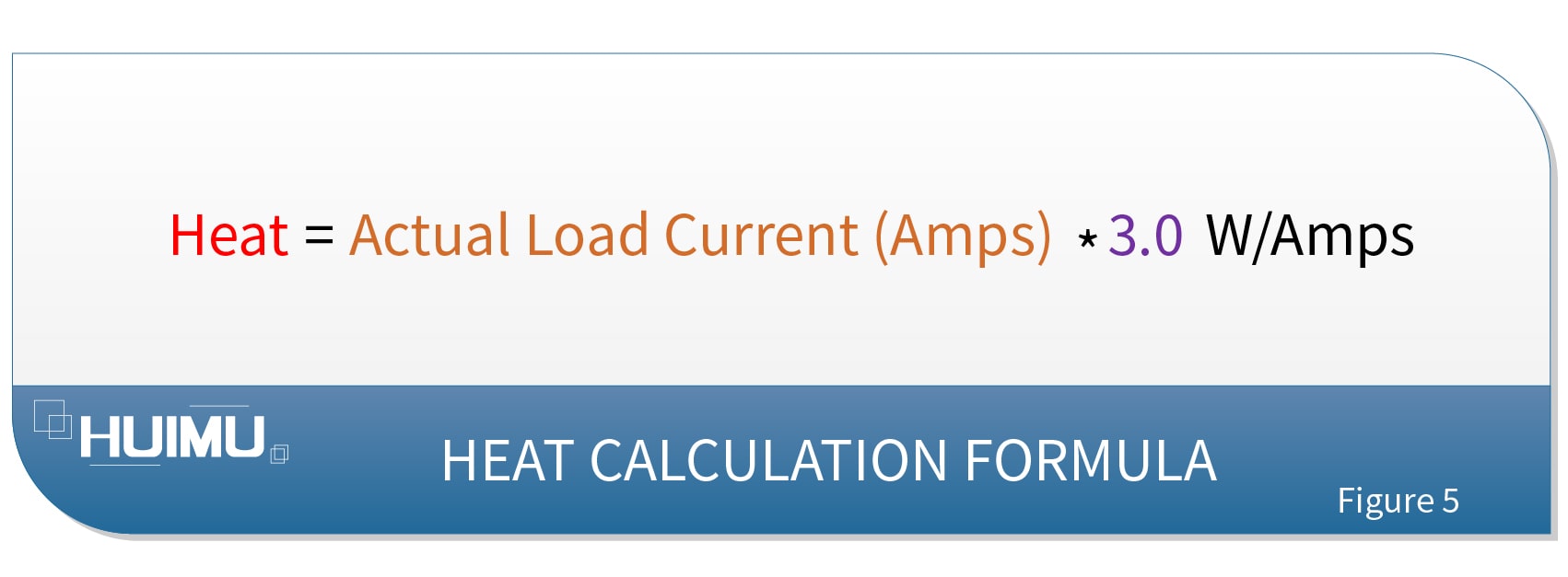
Note: The above formula is suitable for single phase fully-controlled bridge rectifier module.
§3. How to select Heat Sink/Radiator?
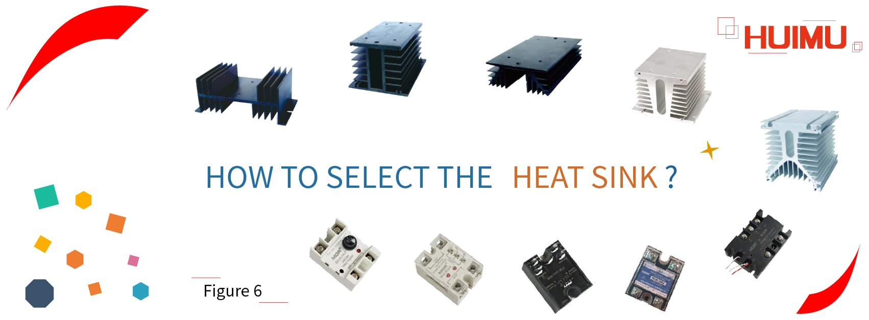
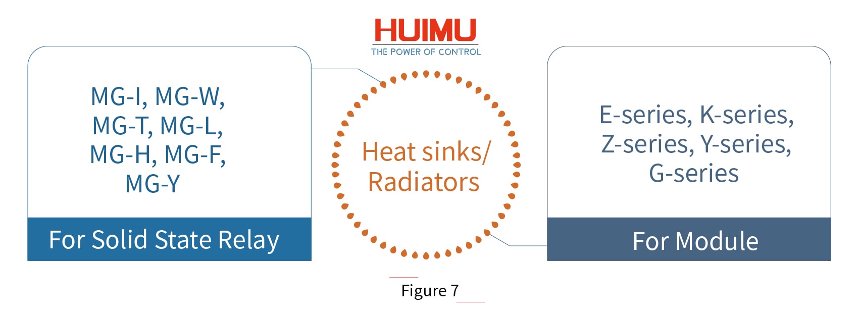
The heat sinks/ radiators produced by our company are divided into two categories, for Solid State Relay and for Solid State Module.
◆ For Solid State Relay: MG-I, MG-W, MG-T, MG-L, MG-H, MG-F, MG-Y.
These seven series are suitable for a variety of single phase solid state relays, single phase AC voltage regulator modules, R series solid state voltage regulators, industrial solid state relays and various three phase AC solid state relays, etc.
◆ For Solid State Module: E series, K series, Z series, Y series, G series.
These series are usually used with an air-cooled fan, suitable for DC commutator modules, voltage regulator modules, rectifier modules, phase-shift trigger modules, thyristor modules, hybrid modules, welding machine modules, etc.
The following are the general applications and selection of some radiators:
⭕ MGR-DT Series Full Isolation Single Phase AC Solid State Voltage Regulator Module
The heat of the whole module = Actual load current (Amps) * 1.5 W/Amps. Customers can select MG-L, MG-H series heat sink according to actual needs.
⭕ MGR-DQZ Series Single Phase Full Isolation Fully-Controlled Solid State Bridge Rectifier Module
The heat of the whole module = Actual load current (Amps) * 3.0 W/Amps. Customers can select MG-L, MG-H series heat sink according to actual needs.
⭕ MGR-STY Series Full Isolation Three Phase AC Solid State Voltage Regulator Module
The heat of the whole module = Actual load current (Amps) * 1.5 W/Amps. Customers can select MG-Y, MG-H series heat sink according to actual needs.
⭕ SSR-3JK Series Three Phase Solid State Phase-Shift Trigger Module (For Solid State Relays)
SSR-3JK and TB-3 generate very little heat, and no heat sink is required.
The SSR-3JK (with TB-3) matches the random solid state relays produced by our company. Customers can build the SSR-3JK system by purchasing the SSR-3JK, the TB-3, three random conduction type SSRs and one heat sink. If three industrial solid state relays are selected, they can be mounted on a Y series module air-cooled radiator with a fan installed to form a power unit; and if three standard solid state relays are selected, they can be mounted on the MG-Y heat sink to form a power unit.
⭕ SX-JK Series Three Phase Solid State Phase-Shift Trigger Module (For Thyristor Circuits)
SX-JKA, SX-JKT, SX-JKZ, SX-JKB, TB-3A, and TB-3Z generate very little heat, and no heat sink is required.

Get in touch with us now!
Please take a minute or two to complete this simple form to get reply in 24 hours, thank you!
*Please check the trash box of your mailbox, if you do not receive our email.


